The implementation of BIM compliance and collaborative processes within the workflow of AEC companies is changing the way we work. Right from the conceptual design phase, the design model is increasingly being understood as the project reference across a range of engineering specializations.
The Importance of a Common Coordinate System
AEC projects are often initiated by an architectural design that uses local coordinates without geospatial referencing. While this may be adequate for collaboration with a structural engineer, workflow problems arise if the project involves civil infrastructure, such as access roads and piped services.
In this case, the civil engineer will require accurate survey coordinates in order to contribute to the shared design model.
The project must now take on a real-world geospatial location and the project must be set up with a real-world coordinate system. An effective
BIM workflow strategy would seek to integrate the relevant survey data at the project's origin, so that the design model has a real world location from start to finish.
Working with Different Coordinate Systems
The advance in mainstream use of Global Positioning Systems (GPS) technology has allowed geodesists to develop global ellipsoid models such as WGS72, GRS80 and WGS84. The World Geodetic System (WGS84) datum is now a widely referenced global positioning coordinate system, but different systems are applied for certain projects in locations where this approximation is not ideal.
Maps, plans and survey calculations are primarily based on two dimensional positions. To make this possible, ellipsoidal values based on a specified datum such as the WGS84, need to be 'projected' onto a plane surface. Here again there are many different projection definitions, usually chosen according to the shape and position of the area to be mapped. The idea is to project with minimum distortion, although no projection will be perfect.
Using Presets in Civil Designer Software
Civil Designer has always allowed projects to be set up within the most widely used datum and projections for both northern and southern coordinate systems. These include the
Local, Transverse Mercator, UTM (Universal Transverse Mercator) and New Zealand Transverse Mercator mapping projections and a host of datum alternatives.
In the latest 8.2 version, Civil Designer simplifies the process further by providing a database of Preset coordinate systems.
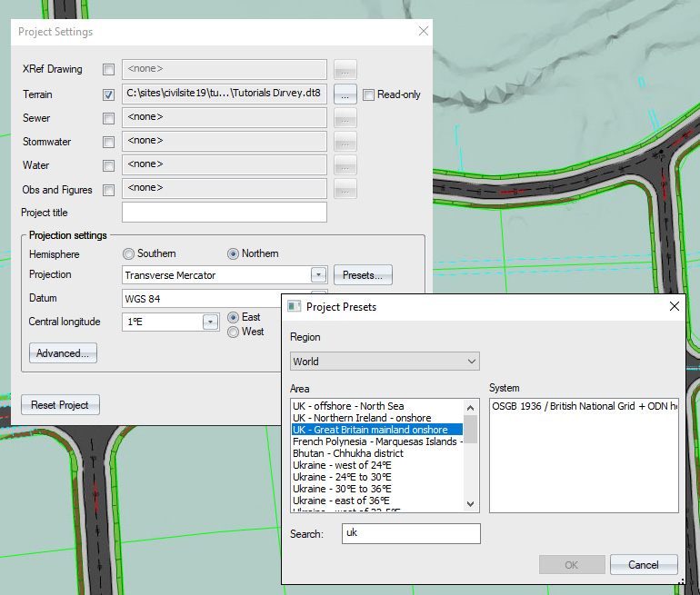
Selecting a coordinate system based on Presets in Civil Designer Software
The Presets option is an alternative to specifying the traditional projection settings and allocates the correct coordinate system according to the
location of the project at hand. In the Project Presets dialog, you can simply choose from various preset options and your selection will automatically
assign all the required projection settings.
CIVIL DESIGNER allows the engineer to quickly implement the appropriate project settings according to the project at hand. A design model
developed 'in-situ' with the correct geo-referencing applied at its early stages, facilitates project workflow and allows all the design experts to
engage with the shared design model.
Common Coordinate Systems Facilitate Project Collaboration
Email info@civildesigner.com for more information about Civil Designer Software.
|